


Single-Mode FC Fiber Optic Connector For High-Precision Optical Network Connections
In optical fiber communication systems, the fiber optic connector is a key component that enables detachable connections between optical fibers, optical modules, and equipment. Its parameter characteristics directly determine the efficiency, stability, and reliability of the entire optical link. From data centers with ultra-high-speed transmission to harsh industrial environments, the performance of fiber optic connectors is critical to the overall system. This article will comprehensively analyze the parameter characteristics of fiber optic connectors from multiple dimensions, including optical performance, mechanical properties, environmental adaptability, interface standards, and material selection, to reveal their technical essence and application value.
1、Optical Performance Parameters: The Core of Signal Transmission
Optical performance parameters are the most critical indicators of fiber optic connectors, directly reflecting their ability to minimize signal loss and maintain transmission integrity. These parameters are strictly defined by international standards such as IEC 61754 and Telcordia GR-326, ensuring consistency across different manufacturers and application scenarios.
Insertion Loss (IL)
Insertion loss refers to the power attenuation caused by the connector when light signals pass through the connection, expressed in decibels (dB). It is caused by factors such as fiber core misalignment, end-face reflection, and mode field mismatch. For high-performance fiber optic connectors, the insertion loss must be extremely low:
For single-mode fiber (SMF) connectors (operating at 1310nm and 1550nm wavelengths), the typical insertion loss is ≤0.2dB, with a maximum limit of 0.3dB (per IEC 61754-4).
For multimode fiber (MMF) connectors (850nm and 1300nm wavelengths), the typical insertion loss is ≤0.3dB, with a maximum of 0.5dB (per TIA-604-5).
The key to achieving low insertion loss lies in the precision of the ferrule. High-quality connectors use zirconia ceramic ferrules with a concentricity error of ≤0.5μm, ensuring that the fiber cores of the connected fibers are aligned within 1μm, minimizing lateral misalignment loss. In addition, the end-face polishing quality of the connector (such as APC polish with an 8° angle) reduces Fresnel reflection, further lowering insertion loss.
Return Loss (RL)
Return loss measures the ratio of reflected power to incident power, also in dB, indicating the connector’s ability to suppress signal reflection. Reflected signals can cause interference in the optical link, leading to bit errors in high-speed transmission. The return loss requirements vary by fiber type and polishing method:
PC (Physical Contact) polish: Common in multimode and some single-mode applications, with return loss ≥45dB (single-mode) and ≥35dB (multimode).
UPC (Ultra Physical Contact) polish: Improves surface smoothness, achieving return loss ≥50dB (single-mode) and ≥40dB (multimode), suitable for high-speed networks like 10Gbps Ethernet.
APC (Angled Physical Contact) polish: Features an 8° angled end-face, reflecting light away from the source, with return loss ≥60dB (single-mode), ideal for long-haul communication and CATV systems where low reflection is critical.
Return loss is highly sensitive to end-face contamination and scratches. Therefore, high-performance connectors often include dust caps and anti-static designs to maintain end-face cleanliness, ensuring stable return loss over time.
Wavelength Range
Fiber optic connectors must support the operating wavelengths of the optical system they serve. The standard wavelength ranges are:
Multimode connectors: 850nm (primary) and 1300nm (secondary), covering short-distance transmission in data centers and local area networks (LANs).
Single-mode connectors: 1310nm and 1550nm (O-band and C-band), supporting long-haul transmission in metropolitan area networks (MANs) and wide area networks (WANs). Advanced connectors also support extended L-band (1565-1625nm) and S-band (1460-1530nm) to meet the needs of dense wavelength division multiplexing (DWDM) systems.
The material of the connector’s ferrule must be compatible with the wavelength range. For example, zirconia ceramics have low absorption in 850-1625nm, making them suitable for all standard wavelengths, while plastic ferrules may have higher absorption in the 1550nm range, limiting their use in single-mode systems.
Mode Field Diameter (MFD) Compatibility
For single-mode connectors, MFD compatibility is critical to reducing insertion loss. The MFD of standard single-mode fiber is 9.2±0.4μm at 1310nm and 10.4±0.5μm at 1550nm. Connectors must ensure that the connected fibers have matching MFDs, as a mismatch of 1μm can increase insertion loss by 0.1dB. High-precision connectors use ferrules with a bore diameter of 126±0.5μm (for 125μm cladding fibers), ensuring that the mode fields overlap sufficiently.
2、Mechanical Parameters: Ensuring Structural Stability and Durability
The mechanical performance of fiber optic connectors determines their reliability during installation, mating, and long-term use. These parameters are designed to withstand physical stress, repeated operations, and environmental vibrations without degrading optical performance.
Insertion and Extraction Force
The force required to mate (insertion) and disconnect (extraction) the connector must be within a reasonable range to ensure ease of operation while preventing accidental disconnection:
Insertion force: Typically ≤30N (for LC, SC, ST connectors), ensuring that operators can mate connectors without excessive effort.
Extraction force: ≥2N (minimum) and ≤20N (maximum), preventing accidental disconnection due to vibration while allowing easy removal when needed.
These forces are controlled by the connector’s locking mechanism. For example, SC connectors use a push-pull latching system with a spring-loaded design, while LC connectors use a click-in mechanism, both designed to maintain consistent insertion/extraction forces over thousands of mating cycles.
Durability (Mating Cycles)
Fiber optic connectors must withstand repeated mating and unmating without significant degradation in optical performance. International standards specify a minimum of 500 mating cycles for general-purpose connectors, but high-reliability models (e.g., those used in data centers) can achieve 1000 cycles or more. After the specified cycles, the insertion loss should not increase by more than 0.2dB, and return loss should remain within the original limits.
Durability is achieved through high-quality materials: zirconia ceramic ferrules have a hardness of 9 Mohs (second only to diamond), resisting wear even after repeated contact. The connector housing, often made of polyetherimide (PEI) or stainless steel, provides mechanical support and protects internal components from damage.
Ferrule Alignment and Concentricity
The core function of a fiber optic connector is to align the ferrules of two connected fibers with high precision. Key parameters include:
Concentricity error: The deviation between the center of the fiber core and the ferrule’s outer diameter, typically ≤0.5μm for single-mode connectors and ≤2μm for multimode connectors. This ensures that the fiber cores are aligned to minimize lateral misalignment loss.
Axial alignment: The ferrule must be centered along the connector’s axis, with a lateral offset ≤0.5μm. Axial misalignment (end-face gap) is controlled by the connector’s design, ensuring that the fiber end-faces are in physical contact (for PC/UPC/APC) to reduce air gap loss.
To achieve this, high-end connectors use precision-machined ferrules and housings, often with active alignment during assembly to correct for manufacturing tolerances.
Mechanical Strength and Vibration Resistance
Connectors must withstand mechanical stress during installation and operation:
Tensile strength: The connector should resist a pulling force of ≥50N without loosening or damaging internal components, ensuring that cables do not disconnect under tension.
Vibration resistance: When subjected to vibration (10-2000Hz, 10G acceleration), the insertion loss variation should be ≤0.1dB, critical for aerospace and industrial environments where vibration is common.
Shock resistance: After shock testing (100G, 6ms duration), the connector should show no physical damage and insertion loss change ≤0.2dB, ensuring reliability in harsh environments like automotive or military applications.
3、Environmental Performance Parameters: Adaptability to Extreme Conditions
Fiber optic connectors operate in diverse environments, from controlled data centers to outdoor telecom cabinets, and their environmental parameters determine their ability to maintain performance under temperature fluctuations, humidity, corrosion, and contamination.
Operating Temperature Range
The temperature range a connector can withstand without performance degradation is critical for different applications:
Commercial grade: -20°C to +70°C, suitable for indoor environments like offices and data centers.
Industrial grade: -40°C to +85°C, designed for factory floors, outdoor cabinets, and automotive applications.
Military grade: -55°C to +125°C, meeting MIL-STD-883 requirements for aerospace and defense systems.
At extreme temperatures, materials must maintain stability: ceramic ferrules have a low thermal expansion coefficient (≈1×10⁻⁶/°C), preventing dimensional changes that could cause misalignment. The housing material (e.g., high-temperature PEI or stainless steel) resists cracking or deformation, ensuring the connector’s structural integrity.
Humidity Resistance
High humidity can cause corrosion of metal components or condensation on fiber end-faces, increasing insertion loss. Connectors must pass humidity testing:
Exposure to 95% relative humidity (RH) at 40°C for 1000 hours, with insertion loss change ≤0.2dB and no visible corrosion on metal parts (e.g., spring clips, coupling nuts).
For marine or tropical applications, specialized connectors with IP68-rated sealing prevent moisture ingress, ensuring long-term reliability in wet environments.
Corrosion Resistance
In environments with salt spray (coastal areas), industrial chemicals, or pollutants, metal components (e.g., nickel-plated housings, stainless steel ferrules) must resist corrosion:
Salt spray testing (per ASTM B117) for 500 hours, with no red rust or corrosion that could affect performance. The insertion loss change after testing should be ≤0.2dB.
For chemical resistance, connectors with PTFE (Teflon) coatings or stainless steel 316 housings can withstand exposure to acids, alkalis, and solvents, suitable for industrial processing plants.
Contamination Resistance
Dust, oil, and other contaminants on fiber end-faces can significantly increase insertion loss. High-performance connectors include features to resist contamination:
Dust caps: Removable caps protect unused connectors from dust, reducing the need for frequent cleaning.
Self-cleaning designs: Some connectors use special end-face treatments that repel contaminants, preventing them from adhering to fiber end-faces.
IP rating: Connectors with IP65 or IP67 ratings are dust-tight and water-resistant, suitable for outdoor use where exposure to rain or dust is inevitable.
4、Interface Types and Dimensional Parameters: Compatibility and Standardization
Fiber optic connectors come in various interface types, each with specific dimensional parameters to ensure compatibility with corresponding adapters and equipment. The most common interface types include:
LC Connector
Dimensional parameters: Ferrule diameter 1.25mm, connector width 6.2mm, designed for high-density installations (e.g., 1U patch panels with 48 ports).
Key feature: Small form factor (SFF), reducing space usage by 50% compared to SC connectors, ideal for data centers with high port density requirements.
Optical performance: Insertion loss ≤0.2dB (single-mode), return loss ≥50dB (UPC), widely used in 10G/40G/100G Ethernet links.
SC Connector
Dimensional parameters: Ferrule diameter 2.5mm, square housing (10mm×10mm), easy to install with a push-pull mechanism.
Key feature: Low insertion loss variation (<0.1dB) and high repeatability, commonly used in telecom networks and CATV systems.
Optical performance: Supports both single-mode (IL ≤0.2dB) and multimode (IL ≤0.3dB) fibers, with APC versions for low-reflection applications.
ST Connector
Dimensional parameters: 2.5mm ferrule, bayonet locking mechanism, cylindrical housing with a diameter of 12mm.
Key feature: Rugged design, suitable for harsh environments like industrial control systems, though gradually replaced by LC/SC in high-density applications.
Optical performance: Multimode IL ≤0.3dB, single-mode IL ≤0.3dB, with a focus on mechanical reliability over compactness.
MPO/MTP Connector
Dimensional parameters: 12-fiber or 24-fiber array, ferrule pitch 0.25mm, designed for parallel optical links (e.g., 400G Ethernet).
Key feature: High-density connectivity (up to 24 fibers in a single connector), reducing cable clutter in data centers.
Optical performance: Per-fiber insertion loss ≤0.3dB (multimode), ≤0.2dB (single-mode), critical for parallel transmission where all fibers must perform uniformly.
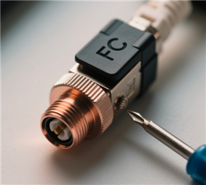
FC Connector
Dimensional parameters: 2.5mm ferrule, screw-on locking mechanism, offering high precision alignment.
Key feature: Excellent stability and low insertion loss, commonly used in high-precision applications such as test and measurement equipment and long-haul telecom networks.
Optical performance: Single-mode IL ≤0.2dB, return loss ≥60dB (APC), making it suitable for DWDM systems.
5、Material Parameters: Impact on Performance and Reliability
The materials used in fiber optic connectors directly influence their optical, mechanical, and environmental performance. Manufacturers select materials based on the application’s requirements for precision, durability, and cost.
Ferrule Materials
Zirconia ceramic: The gold standard for ferrules, with high hardness (9 Mohs), low friction, and excellent dimensional stability. Its thermal expansion coefficient (1×10⁻⁶/°C) matches that of silica fiber (0.5×10⁻⁶/°C), minimizing alignment changes with temperature.
Phosphor bronze: Used in some low-cost ferrules, offering good conductivity but lower hardness than ceramic, suitable for low-cycle applications.
Plastic (polyimide): Found in disposable or low-cost connectors, with lower precision (concentricity error ≥2μm) and limited temperature resistance, suitable for temporary connections.
Housing Materials
Polyetherimide (PEI): A high-performance plastic with excellent heat resistance (Tg = 217°C), mechanical strength, and flame retardancy (UL94 V-0), widely used in commercial and industrial connectors.
Stainless steel (304/316): Offers superior corrosion resistance and mechanical strength, ideal for marine, industrial, and military applications, though heavier and more expensive than plastic.
Brass (nickel-plated): Provides good conductivity and machinability, used in connectors with metal housings, though prone to corrosion in humid environments without proper plating.
Cable Jacket and Reinforcement Materials
The cable portion of the connector includes a jacket and reinforcement to protect the fiber:
Jacket materials: PVC (flame retardant), LSZH (low smoke zero halogen), or TPU (thermoplastic polyurethane) for flexibility and durability.
Reinforcement: Kevlar aramid yarns or steel wires provide tensile strength, ensuring the fiber is not damaged during installation or use.
6、Application-Specific Parameter Requirements
Different application scenarios impose unique demands on fiber optic connectors, leading to specialized parameter optimizations:
Data Center Connectors
High density: LC and MPO connectors with small form factors, supporting 1U patch panels with 96+ ports.
Low latency: Insertion loss ≤0.2dB to minimize signal delay in high-speed links (400G/800G Ethernet).
Quick mating: Push-pull or click-in mechanisms for fast installation, with durability ≥1000 mating cycles to handle frequent reconfigurations.
Telecom Network Connectors
Low reflection: APC polish with return loss ≥60dB to prevent signal interference in long-haul DWDM systems.
Weather resistance: Industrial-grade temperature range (-40°C to +85°C) and IP66 sealing for outdoor ODN (Optical Distribution Network) cabinets.
Industrial Connectors
Vibration resistance: Insertion loss variation ≤0.1dB under 10G vibration, critical for factory automation and robotics.
Hermetic sealing: IP67-rated to prevent dust and water ingress in harsh industrial environments.
Aerospace and Military Connectors
Extreme temperature tolerance: -55°C to +125°C, meeting MIL-STD-202 requirements.
Radiation resistance: Tested to withstand 100kRad of ionizing radiation without performance degradation, ensuring reliability in space or nuclear applications.
7、Testing and Compliance Standards
To ensure consistency and reliability, fiber optic connectors must comply with international standards that define parameter testing methods and limits:
IEC 61754: Specifies dimensional, optical, and mechanical requirements for fiber optic connectors, with parts dedicated to specific types (e.g., IEC 61754-4 for SC, IEC 61


