


Optical Fiber Joint Box With Fusion Tray For Cable Termination In FTTH And FTTB Networks
I. Structural Design Parameters
The structural design of the Optical Fiber Terminal Box is the basis for its functionality. Reasonable structural parameters can not only ensure the safe storage and management of optical fibers but also improve the convenience of installation and maintenance.
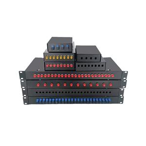
In terms of size specifications, common terminal boxes are divided into three categories: desktop, wall-mounted, and rack-mounted according to different installation scenarios. Desktop terminal boxes usually have a length of 150-300mm, a width of 100-200mm, and a height of 50-100mm. These terminal boxes are compact and suitable for fiber access in homes or small offices. Wall-mounted terminal boxes are relatively more compact in size to adapt to the space constraints of wall installation, with a length generally ranging from 200-400mm, a width of 150-250mm, and a height of 80-150mm. Some products are also designed with foldable panels to further save installation space. Rack-mounted terminal boxes are mainly used for standard cabinet installation in data centers or equipment rooms. Their height usually follows the U standard, with common ones being 1U (44.45mm), 2U (88.9mm), etc. The width matches the cabinet at 19 inches (482.6mm), and the depth varies from 200-400mm depending on the fiber capacity.
Fiber capacity is one of the core parameters in structural design, representing the number of fiber cores that the terminal box can accommodate. According to different application requirements, the fiber capacity of terminal boxes ranges from a minimum of 4 cores to a maximum of 288 cores or more. Small terminal boxes such as 4-core, 8-core, and 12-core are mostly used for home broadband access or small local area networks; medium-sized terminal boxes such as 24-core, 48-core, and 72-core are suitable for building or enterprise-level networks; large terminal boxes such as 96-core, 144-core, and 288-core are mainly used in backbone network nodes or high-density fiber connections in data centers. It is worth noting that the fiber capacity is usually marked as the "maximum number of fiber cores that can be accommodated". In actual use, the way of fiber deployment and reserved space should be considered. Generally, it is recommended that the actual installed number of cores does not exceed 80% of the maximum capacity to ensure good heat dissipation and maintenance space for optical fibers.
The internal structure layout parameters are also crucial. The terminal box usually contains functional areas such as a fiber fusion splicing area, a fiber storage area, an adapter installation area, and a cable entry area. The size of the fusion splicing area must meet the installation requirements of the fusion splice tray. Each fusion splice tray can accommodate 12 to 48 splice points, and a spacing of at least 5mm must be reserved between fusion splice trays to facilitate fusion splicing operations and heat dissipation. The storage area is used to coil excess optical fibers, and its coiling radius is a key parameter. Depending on the type of optical fiber, the minimum coiling radius of single-mode optical fiber is not less than 30mm, and that of multi-mode optical fiber is not less than 25mm, to avoid increased transmission loss caused by excessive bending of the optical fiber. The adapter installation area must be designed with corresponding mounting holes according to the type of adapter (such as SC, LC, FC, ST, etc.). The hole spacing is usually 12mm or 16mm to ensure that the adapter is installed firmly and can be plugged in smoothly. The cable entry area must be equipped with a sealing device, which can adapt to the introduction of optical cables with different outer diameters. The common outer diameter range of optical cables is 5-20mm. The sealing grade of the entry area must reach IP65 or higher to prevent dust and water vapor from entering.
The parameters of the shell material also directly affect the structural stability and protective performance of the terminal box. The terminal box shell is usually made of high-quality cold-rolled steel plate, ABS engineering plastic, or SMC composite material. The thickness of the cold-rolled steel plate shell is generally 1.2-2mm. After surface treatment such as pickling, phosphating, and electrostatic spraying, it has good rust and corrosion resistance, and the protection grade can reach IP66; the thickness of the ABS engineering plastic shell is 2-3mm, which has the characteristics of light weight, good insulation performance, and high impact strength, with an impact strength of more than 15kJ/m², suitable for indoor dry environments; the SMC composite material shell has excellent weather resistance and flame retardancy, with a flame retardant grade of UL94 V-0, suitable for outdoor or humid environments.
II. Optical Performance Parameters
The optical performance of the Optical Fiber Terminal Box is the core to ensure the quality of optical fiber communication, and its parameters are directly related to key indicators such as signal transmission loss, stability, and bandwidth.
Insertion loss is one of the most important parameters in optical performance, which refers to the degree of power attenuation of optical signals after passing through the terminal box. For single-mode fiber terminal boxes, the insertion loss should be ≤0.3dB at the two commonly used wavelengths of 1310nm and 1550nm; for multi-mode fiber terminal boxes, the insertion loss should be ≤0.2dB at 850nm and 1300nm wavelengths. The magnitude of insertion loss mainly depends on the quality of the adapter, the fusion quality of the optical fiber, and the internal fiber routing technology. High-quality terminal boxes will control the insertion loss to the minimum level through precise adapter positioning structures and optimized fiber path design, ensuring efficient signal transmission.
Return loss (reflection loss) reflects the ability of the terminal box to suppress reflected light. Excessive reflected light will cause signal interference and affect communication quality. For single-mode fiber terminal boxes, the return loss should be ≥50dB at 1310nm wavelength and ≥55dB at 1550nm wavelength; for multi-mode fiber terminal boxes, the return loss should be ≥40dB at both 850nm and 1300nm wavelengths. The level of return loss is closely related to the end-face treatment method of the adapter. Adapters with APC (Angled Physical Contact) end-faces can provide higher return loss, which is suitable for high-speed communication systems sensitive to reflected light, while adapters with PC (Physical Contact) end-faces have relatively lower return loss and are mostly used in general communication scenarios.
The operating wavelength range is an important parameter for the terminal box to adapt to different optical fiber communication systems. Wavelengths widely used in modern optical fiber communication systems include 850nm (multi-mode short-distance), 1310nm (single-mode medium-distance), 1550nm (single-mode long-distance), and 1625nm (test wavelength), etc. High-quality terminal boxes should maintain stable optical performance in the full wavelength range of 850-1625nm, and the variation of insertion loss and return loss should not exceed 0.1dB, to meet the compatibility requirements of different communication systems.
The fiber type compatibility parameter determines whether the terminal box can adapt to different types of optical fibers. The terminal box should support the connection of single-mode fibers (G.652D, G.655, G.657A, etc.) and multi-mode fibers (OM1, OM2, OM3, OM4). For optical fibers with different outer diameters (such as 0.25mm coated fibers, 0.9mm tight-buffered fibers, 2mm/3mm loose-tube fibers, etc.), the fixing and guiding structures inside the terminal box should provide good adaptability to ensure that the optical fibers are not subjected to additional stress in the terminal box and maintain stable transmission performance.
The type and quantity parameters of adapters depend on the interface requirements. The terminal box can be configured with various types of adapters such as SC, LC, FC, ST, etc. Among them, SC and LC adapters are widely used because of their convenient plugging and compact size. The number of adapters matches the fiber capacity of the terminal box. For example, a 24-core terminal box can be configured with 24 SC adapters or 48 LC adapters (LC is a duplex adapter). The insertion loss of the adapter should be ≤0.2dB, the repeatability is ≥1000 insertions and extractions, and the interchangeability should comply with IEC standards to ensure that adapters from different manufacturers can be used interchangeably.
III. Mechanical Performance Parameters
The Optical Fiber Terminal Box is subject to various mechanical forces during installation, transportation, and use, and its mechanical performance parameters directly determine the structural stability and service life of the terminal box.
Impact resistance is an important indicator to measure the ability of the terminal box to resist external impacts. According to IEC 61300-2-2 standard, the terminal box should withstand the impact test of free fall from a height of 1 meter to the cement ground. After the test, the terminal box shell should not have cracks, deformation, or other damages, internal components should not be loose or fall off, and the change of optical performance parameters should be within the allowable range (insertion loss change ≤0.3dB). For rack-mounted terminal boxes, they should also be able to withstand the collision force during the installation and maintenance of equipment in the cabinet, and the impact strength of their front panel should be ≥50N.
Compressive performance is mainly for rack-mounted terminal boxes. When installed in a standard cabinet, other equipment may be placed on top of the terminal box, so it needs to have a certain compressive capacity. According to industry standards, rack-mounted terminal boxes should withstand a static pressure of 500N on the top for 1 hour. After that, the shell should not have obvious deformation, the internal structure should not be damaged, and the optical performance should remain stable (insertion loss change ≤0.2dB). Desktop and wall-mounted terminal boxes have relatively lower compressive performance requirements, usually able to withstand 200N of static pressure to meet the use needs.
Vibration resistance test is used to simulate the vibration impact of the terminal box during transportation or use. The terminal box should withstand a sinusoidal vibration test with a frequency of 10-500Hz and an amplitude of 0.35mm. In the vibration direction (horizontal and vertical directions, 1 hour each), the internal components of the terminal box should not be loose, the fiber connection should not be interrupted, and the insertion loss change after the test should be ≤0.3dB. For terminal boxes installed along transportation tools (such as subways, trains), their vibration resistance requirements are higher, and they need to withstand wide-frequency vibration with a frequency of 1-2000Hz.
Tensile performance mainly targets the optical cable entry part, testing the connection strength between the terminal box and the optical cable. Depending on the type of optical cable, the optical cable tensile strength requirements for the terminal box are different: for outdoor optical cables, the terminal box should withstand a tensile force of ≥1500N; for indoor optical cables, the tensile strength requirement is ≥500N. During the tensile test, the optical cable should not be pulled out of the terminal box, the terminal box shell and internal fixing structure should not be damaged, and the optical performance change should be ≤0.2dB. In addition, the terminal box should also be able to withstand a certain lateral tensile force, with a lateral tensile strength of ≥500N, to prevent the optical cable from being damaged by lateral force.
Sealing performance is a key mechanical performance parameter to ensure that the inside of the terminal box is not affected by the external environment, usually expressed by the protection level (IP level). The protection level of indoor terminal boxes is generally IP54, which can prevent dust from entering and affecting the normal operation of the equipment, and can withstand water spraying from any direction without damage; the protection level of outdoor terminal boxes needs to reach IP65 or higher. IP65 level means that it is completely dust-tight and can withstand low-pressure water spraying (water sprayed from a nozzle) without damage. Terminal boxes used in special environments (such as underwater or humid environments) can reach IP68 protection level, which can be immersed in water for a long time at a certain depth without water ingress. The sealing performance is mainly achieved by the sealing ring of the terminal box shell and the sealing device in the cable entry area. The sealing ring is usually made of aging-resistant silicone rubber material, with a hardness of 60±5 Shore A, and the compression amount is controlled between 20%-30% to ensure a good sealing effect.
Mechanical durability parameters reflect the performance stability of the terminal box after long-term use. The movable parts such as the door lock and hinge of the terminal box should withstand ≥1000 opening and closing operations, and after the operations, they should still maintain good locking performance and sealing performance. The plug-in durability of the adapter should be ≥500 times, and the insertion loss change after 500 plug-ins should be ≤0.3dB, ensuring the stability of the fiber connection during long-term use.
IV. Environmental Adaptability Parameters
The Optical Fiber Terminal Box is used in a variety of complex environments, from dry indoor equipment rooms to humid outdoor open environments. Its environmental adaptability parameters determine the reliable operation ability of the terminal box under different environmental conditions.
The operating temperature range is the most basic parameter in environmental adaptability. The operating temperature of indoor terminal boxes is usually -5℃~+40℃, suitable for constant temperature equipment rooms or office environments; outdoor terminal boxes need to have a wider operating temperature range, generally -40℃~+65℃, to cope with extreme high and low temperature environments. In the temperature cycle test, the terminal box must undergo 5 cycles in the range of -40℃~+65℃ (each cycle includes 2 hours of low-temperature holding, 2 hours of high-temperature holding, and a temperature change rate of ≤10℃/minute). After the test, the terminal box's optical performance change should be ≤0.5dB, the shell should not have cracks, deformation, or other damages, and internal components should not have condensation.
The relative humidity parameter reflects the adaptability of the terminal box in humid environments. The terminal box should work normally in an environment with a relative humidity of 5%-95% (no condensation). For outdoor terminal boxes, it should also withstand a condensation environment of 95%-100%. In the constant damp heat test, the terminal box is placed in an environment with a temperature of 40℃ and a relative humidity of 93% for 10 days. After the test, there should be no obvious water vapor condensation inside the terminal box, the optical performance change should be ≤0.5dB, metal parts should not have rust, and plastic parts should not have deformation or cracking.
Salt spray resistance is an important parameter for terminal boxes used in coastal areas or industrial pollution environments. According to IEC 60068-2-11 standard, the terminal box must undergo a neutral salt spray test under the following conditions: temperature 35℃, salt solution concentration 5%, pH value 6.5~7.2, continuous spray for 48 hours. After the test, the metal parts of the terminal box should not have obvious rust (rust grade not lower than 9), plastic parts should not have discoloration or cracking, the optical performance change should be ≤0.5dB, and the sealing performance should still maintain IP65 or higher.
UV resistance is mainly for terminal boxes installed outdoors in the open air. Long-term exposure to sunlight will cause aging of the shell material. The terminal box shell should withstand the UV aging test under the following conditions: UV wavelength 313nm~340nm, irradiance 0.71W/m², temperature 60℃, test time 168 hours. After the test, the shell should not have obvious discoloration, cracking, or chalking, the impact strength retention rate should be ≥80%, and the sealing performance should not decrease.
Dustproof performance is a guarantee for the normal operation of the terminal box in dusty environments. According to the IP dustproof grade, IP6X grade means that the terminal box is completely dust-tight, with no dust deposition inside. In the dustproof test, the terminal box must be placed in a test chamber with a dust concentration of 2kg/m³ for 8 hours. After the test, the dust deposition on internal components should be ≤0.1g/m², and the optical performance change should be ≤0.3dB, ensuring that dust will not affect the transmission performance of optical fibers and the mechanical performance of the terminal box.
Corrosion resistance is mainly for the metal parts of the terminal box, such as the shell, bracket, screws, etc. The surface treatment of metal parts should comply with relevant standards. The cold-rolled steel plate shell is usually treated with galvanizing and electrostatic spraying, with a coating thickness of ≥8μm and a coating thickness of ≥60μm, and the corrosion resistance should pass the 48-hour salt spray test; stainless steel parts (such as screws) should be made of 304 or 316 stainless steel. 304 stainless steel is suitable for general corrosive environments, while 316 stainless steel is suitable for highly corrosive environments (such as coastal areas) and has better corrosion resistance than 304 stainless steel.
Seismic performance is an important parameter for terminal boxes used in earthquake-prone areas. The terminal box should withstand a certain seismic intensity. According to GB 50260-2013 "Code for Seismic Design of Electric Power Facilities", in areas with a seismic intensity of 8 degrees, the terminal box should withstand seismic loads with a horizontal acceleration of 0.2g and a vertical acceleration of 0.1g. After the seismic test, the terminal box should not have structural damage, the optical performance change should be ≤0.5dB, and the connections should not be loose.
V. Safety Certification and Environmental Protection Parameters
As a key equipment in communication networks, the Optical Fiber Terminal Box must meet relevant standards and certification requirements in terms of safety performance and environmental protection performance to ensure safety during use and friendliness to the environment.
Electrical safety certification is an important guarantee for the safety performance of the terminal box. The metal shell of the terminal box should have good grounding performance, and the grounding resistance should be ≤1Ω to prevent static accumulation or electric leakage from causing harm to equipment and personnel. For terminal boxes installed in flammable and explosive environments, they must pass explosion-proof certification (such as ATEX certification or IECEx certification), and the explosion-proof grade of their shell should not be lower than Ex d IIB T6 to ensure that they will not cause explosions in potentially explosive environments. In addition, the insulation resistance of the terminal box should be ≥1000MΩ (measured under 500V DC voltage), and the dielectric strength should withstand 1500V AC voltage for 1 minute without breakdown or flashover, ensuring good electrical insulation performance.
Flame retardant performance parameters are used to evaluate the fire resistance of the terminal box in case of fire. The flame retardant grade of the terminal box shell material should reach UL94 V-0, that is, in the vertical burning test, the burning time of the material should not exceed 10 seconds each time, the total burning time of two times should not exceed 30 seconds, and there should be no molten droplets to ignite the degreased cotton below. For terminal boxes installed in high-rise buildings or crowded places, flame retardant performance is particularly important, which can effectively delay the spread of fire and gain time for personnel evacuation and fire fighting.
Environmental protection parameters mainly involve the environmental friendliness of the terminal box materials, and meeting the requirements of the RoHS directive is the basic standard. The content of harmful substances such as lead (Pb), mercury (Hg), cadmium (Cd), hexavalent chromium (Cr6+), polybrominated biphenyls (PBBs), and polybrominated diphenyl ethers (PBDEs) in the plastics, metals, electronic components, and other materials used in the terminal box should meet the RoHS limit requirements (the limits for lead, mercury, hexavalent chromium, PBBs, and PBDEs are 0.1%, and the limit for cadmium is 0.01%). In addition, the packaging materials of the terminal box should use recyclable and degradable environmental protection materials to reduce environmental pollution.
The aging resistance of materials is also an important embodiment of environmental protection and safety performance. The plastic materials (such as ABS, PC) used in the terminal box should have good weather resistance, not easy to age, discolor, or crack during long-term use, and their oxidation induction time (OIT) should be ≥20 minutes (measured at 200℃). The aging resistance of the rubber sealing ring should comply with ISO 188 standard. After aging at 100℃ for 70 hours, the hardness change should not exceed ±15 Shore A, the tensile strength change rate should not exceed ±30%, and the elongation at break change rate should not exceed ±50%, ensuring reliable long-term sealing performance.
To sum up, the parameter characteristics of the Optical Fiber Terminal Box cover many aspects such as structural design, optical performance, mechanical performance, environmental adaptability, and safety certification. These parameters are interrelated and interact, jointly determining the overall performance and applicable scenarios of the terminal box. In the actual selection process, it is necessary to comprehensively consider various parameter indicators according to specific application environments, fiber types, capacity requirements, and other factors, and select the most suitable terminal box products to ensure the stable and efficient operation of the optical fiber communication network. With the continuous development of optical fiber communication technology, the parameter characteristics of the Optical Fiber Terminal Box are also constantly optimized. In the future, it will develop towards higher capacity, lower loss, stronger environmental adaptability, and more environmental protection, providing more reliable interface guarantee for the next-generation communication network.


